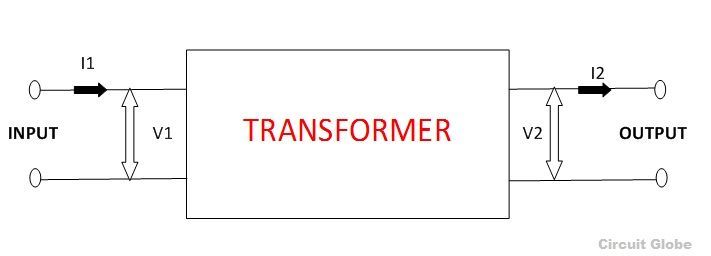
A Transformer is a static electrical machine which transfers AC electrical power from one circuit to the other circuit at the constant frequency, but the voltage level can be altered that means voltage can be increased or decreased according to the requirement.
It works on the principle of Faraday’s Law of Electromagnetic Induction which states that “ the magnitude of voltage is directly proportional to the rate of change of flux.”
A transformer is a device that
- transfers electric power from one circuit to another
- it does so without a change of frequency
- it accomplishes this by electromagnetic induction and
- where the two electric circuits are in mutual inductive influence of each other.
Contents:
- Necessity of a Transformer
- Construction of a Transformer
- Types of Transformer
- EMF Equation of a Transformer
- Losses in the Transformer
- Efficiency of the transformer
Necessity of a Transformer
Usually, electrical power is generated at 11Kv. For economical reasons AC power is transmitted at very high voltages say 220 kV or 440 kV over long distances. Therefore a step-up transformer is applied at the generating stations.
Now for safety reasons the voltage is stepped down to different levels by step down transformer at various substations to feed the power to the different locations and thus the utilisation of power is done at 400/230 V.
If (V2 > V1) the voltage is raised on the output side and is known as Step-up transformer
If (V2 < V1) the voltage level is lowered on the output side and is known as Step down transformer.
Construction of a Transformer
It mainly consists of
- Magnetic circuit (consisting of core, limbs, yoke and damping structure).
- Electrical circuit (consisting of primary and secondary windings)
- Dielectric circuit (consisting of insulations in different forms and used at different places)
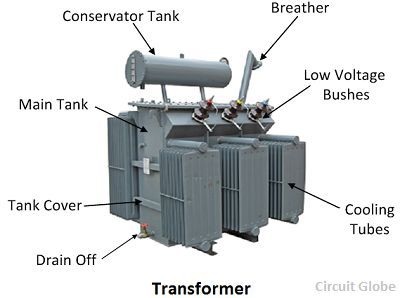
- Tanks and accessories (conservator, breather, bushings, cooling tubes, etc.)
Types of Transformer
The various types are described below
- Position of the windings concerning the core
- Core type
- Shell type
- According to the transformation ratio or number of turns in the windings
- Step up
- Step down
3. Types of services
- Power transformer
- Distribution transformer
- Instrument transformer
- Current transformer
- Potential transformer
- Auto-transformer
4. On the basis of the supply
- Single-phase
- Three-phase
5. On the basis of cooling
- Air Natural (AN) or Self air-cooled or dry type
- Air ForceD (AF) or Air Blast type
- Oil Natural Air Natural (ONAN)
- Oil Natural Air Forced (ONAF)
- Oil Forced Air Forced (OFAF)
- Oil Natural Water Forced (ONWF)
- Oil Forced Water Forced (OFWF)
EMF Equation of the Transformer
EMF Equation is given below
N1 = No. of turns in primary
N2 = No. of turns in secondary
Φm = Maximum flux in core in webers
= Bm × A
f = Frequency of a.c. input in Hz
Where E1 and E2 are the voltages and N1, N2 is the number of turns in the primary and the secondary windings respectively.
Losses in the Transformer
- Core or iron losses
- Hysteresis loss
- Eddy current loss
- Copper losses
- Stray losses
Efficiency of the Transformer
Transformer efficiency is defined as the ratio of the output power to the input power and is expressed in the equation below

This is all about the Transformer. Keep reading.


